Generic HID Software
Screen Layout
The Generic HID software is used to design a HID device. Components are virtually connected to the microcontroller board, and the firmware is generated and downloaded to the device. The layout of the Generic HID software is shown below.
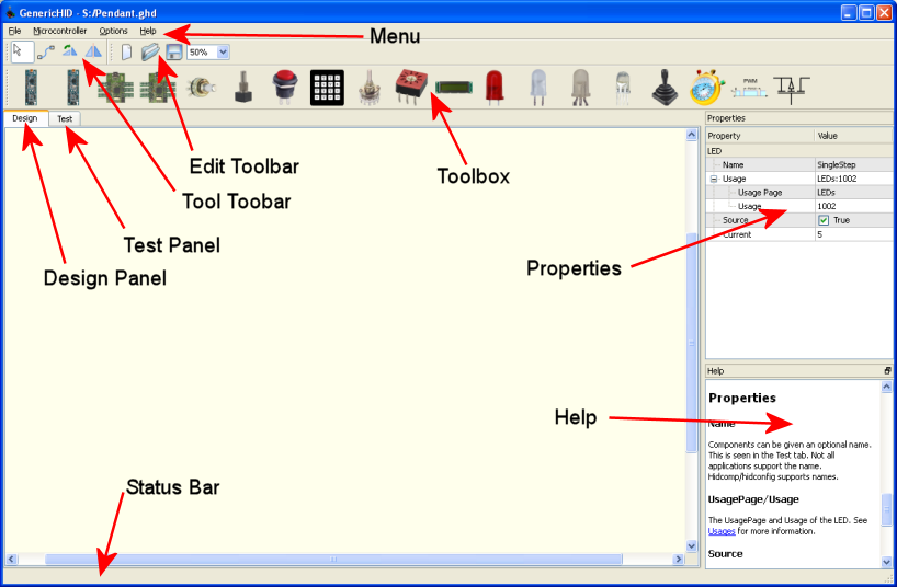
Menu
The following menu items are available.
File
| New | Creates a new Generic HID device configuration. |
| Open | Opens an existing Generic HID device configuration. The extension .ghd is used for Generic HID device configurations. |
| Save | Saves the current device configuration. |
| Save As | Saves the current device configuration, but prompts for a new name. |
| Exit | Exits the applications |
Microcontroller
| Program | Programs the connected microcontroller with the currently loaded configuration. The configuration is verified before the Program dialog is presented. |
| Export | Exports the current configuration as a microcontroller configuration description. The extension .mcd is used for microcontroller configuration descriptions. .mcd files are used to program the microcontroller. Generic HID is a visual editor for the .mcd files, but only supports a subset of functions. If there is a feature needed that Generic HID doesn't support, the current configuration can be exported as an .mcd file, edited, then imported and programmed. Generic HID currently has a fixed number of I/O pins on the KeyMatrix, Rotary Switch and Coded Rotary Switch. |
| Import and Program | Imports an existing .mcd file and programs the microcontroller with the data, as described in "Export". |
Options
| Debug | Toggles debug. This generates volumous amounts of debug to stderr in Linux, and the system debug output device in Windows. |
Help
| About | Shows the about box. |
Edit Toolbar
The Edit Toolbar provides buttons to perform the standard editing operations, also found in the File menu.
| New. Create a new Generic HID configuration. | |
| Open. Open an existing configuration. | |
| Save. Save the existing configuration. | |
| Zoom Combo | Specifies the Zoom percentage on the Design workspace. |
Tool Toolbar
The Tool Toolbar contains the tools used to manipulate the Generic HID configuration.
| Select | Use the select tool to select components on the Design workspace. A component can be deleted when it is selected by pressing the Delete key. When an item is selected, its properties can be changed. | |
| Wire | Create a wire link between two components. Wires are
restricted to which pins they can be connected to. For example, a
Digital Encoder can only be wired to microcontroller pins that support
interrupts. The cursor changes shape according to whether you can
|
|
| Rotate | With this tool selected, clicking on a component will rotate them. Any attached wires will spin too. | |
| Mirror | With this tool selected, the component will mirror horizontally. To mirror vertically, mirror horizontally first, then use the rotate tool. An unfortunate side effect of mirroring a component is all the text labels get mirrored too. |
Toolbox
The tool box contains all the boards and components that can combined to make a Generic HID device. Tools are placed on the design surface by dragging them from the toolbar.
| Stock AT90USBKey | This is a stock AT90USBKey board. A large number of I/O pins are disabled because they are used by the demo peripherals. | |
| Stripped AT90USBKey | The stripped AT90USBKey has had most of the peripheral parts removed, reclaiming most of the I/O pins. | |
| Stripped AT90USBKey with wizbang wings | This is a stripped AT90USBKey with wizbang wings attached. The pins are laid out according the positioning of the wizbang wings. | |
| Stripped AT90USBKey with wizbang wings and IDC connectors | This is a stripped AT90USBKey with wizbang wings attached. It also has standard 0.1x0.1 5x2 headers attached and a matching IDC connector is used to connect wires to the pins. The I/O pins on the board are laid out linearly, in the order they appear out of the connecting ribbon cable. | |
| GenericHID 1.0 Custom Board | This is a custom board. Similar to the AT90USBKey boards except it is a bigger, has screw terminals and high power switching. | |
| Potentiometer | A potentiometer. This device is used to represent any analogue input. This component can only connect to an ADC pin. | |
| Digital Encoder | A digital encoder. The two wires of the digital encoder, A and B, can only connect to interrupt ports. There are 16 interrupt ports. | |
| Button | A regular button, or switch. This device is used to represent any single bit input. This can be a momentary push button, or a toggle switch. Usually wired so that the button shorts the pin to ground when pressed, using the internal pull-up resistor. | |
| Key Matrix | The Key Matrix is used to wire up keypads, or to make efficient use of I/O pins to wire up a lot of buttons. | |
| Rotary Selector Switch | A one-of-n selector switch. Uses the I/O pins inefficiently. One pin is used for each option. | |
|
|
Coded Rotary Selector Switch | Like the rotary selector switch above, except the output of the selector is binary encoded. A 16 way selector only uses 4 I/O pins. |
| LCD | The LCD. Character LCD Modules that use the HD44780U or compatible driver chip. These are your stock modules that you can get everywhere. Common sizes include 8x1, 16x2, 20x2, 40x2, 20x4. There are also some 40x4 displays available which can be used by treating them as separate displays (they have two E pins). | |
| LCD SPI | The LCD SPI is a non-standard custom LCD display. It is built from a 320x240 RGB TFT graphic LCD. The project to build it is documented here. The device connects to the SPI interface of the microcontroller, which means there is only one place to connect the display. | |
| LED | An LED, or a single bit output. Be careful that you do not draw too much current to light LEDs or the microcontroller on the demo boards will be damaged. | |
| Bi-Colour LED | A bi-colour LED. At Frank's Workshop, a bi-colour LED is a two leg LED, with two LEDs inside the package with the anode of one LED connected to the cathode of the other. Power it one way and you get one LED. Reverse the voltage polarity and you light the other. Again, be careful that you do not draw too much current to light LEDs or the microcontroller on the demo boards will be damaged. | |
| Tri-Colour LED | A tri-colour LED. At Frank's Workshop, a tri-colour LED is a three leg LED, with two LEDs inside the package with either the anodes connected, or the cathodes connnected. You can light one, two, or none of the LEDs independantly. Again, be careful that you do not draw too much current to light LEDs or the microcontroller on the demo boards will be damaged. | |
| RGB LED | Am rgb LED. An RGB LED is a three LEDs in one package, a red, green and blue one, typically with the anodes, or the cathodes connnected. You can light one, two, or none of the LEDs independantly. Have I mentioned that you need to be careful that you do not draw too much current to light LEDs or the microcontroller on the demo boards will be damaged? | |
|
|
Directional Switch (HatSwitch) | The directional switch, or hat switch. This is a controller that specifies direction by which buttons are being pressed. This can be disk, like on a game pad, or a joystick, like those found on arcade machines. |
| Counter | A counter. This counts. | |
| PWM | A PWM output. | |
| Power Switch | Used to define the power the HiPower switch is connected to. |
Properties
The properties panel allows the properties of components to be changed. When a component is selected, the properties panel is populated the components properties. Also, the Help panel will also bring up the help for that component. Selecting a property will move the help to a description of the property.
Help
The Help panel displays context sensitive help. If a component is selected, the help for the component is selected. If a component's property is selected, the help for that property is selected. If no component is selected, the help index is displayed.
The Help files are in HTML format, so they can be navigated by clicking on the hyperlinks.
Design Panel
There are two tabs in the application. One is the Design panel.
The Design panel is the working area where components are placed, and wires laid. The are can be zoomed into, or scrolled with scroll bars. The are is a fixed size, more than large enough for any HID device, but it will not expand if components are drag outside the region.
Test Panel
The test panel provides an area to test the new Generic HID device. The image below shows a minimal device.
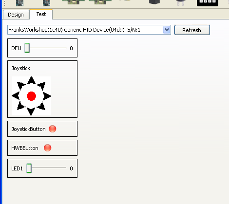
All known component types are displayed. Buttons, or 1 bit inputs are shown as red/green lights. Inputs with large values, such as joysticks and encoders, are shown as a percent bar. Directional switches (or hat switches) are shown as a hat switch symbol. Simple LED outputs are shown as check boxes. Outputs with values greater than 1 are shown as a slider switch. LCDs are shown as a working LCD.
Things that aren't understood may be displayed anyway. The image above shows the "DFU" control. All Generic HID knows about this its name (because the name is reported by the device), and that it is an integer 4 byte number. DFU, Device Firmware Upgrade, is a Generic HID command that sets the device into boot loader mode to upgrade the firmware.
The test panel may misbehave if a device is disconnected when being tested. Also, the Program menu option is not available while in the test panel. Switch back to design before testing.
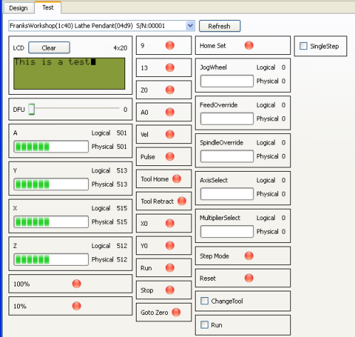
The image below shows a full device, with lots of potentiometer and encoder inputs, lots of buttons and LEDs, and an LCD.
Programming
The programmer is built into the Generic HID software, so there is not need to jump around between applications, converting file formats, etc, unless you really want to. The Generic HID programmer is built on the dfuprogrammer to perform the programming. The AT90USB1287 comes preloaded with bootloader firmware, and fuses set so that bootloader cannot be accidently erased. The AT90USB1287 can always be reprogrammed.
The programmer is launched from the Microcontroller | Program menu. It launches the following dialog. The Program menu is disabled when the Test panel is active.

The dialog contains the following bits...
| Refresh | The refresh button is used to re-read the list of usb devices connected to the computer and update the status of this dialog box. Normally this isn't needed as refreshes are done automatically every second or so. |
| USB Device Located | The USB Device Located light will be green if it can detect a suitable device. This can either be an active Generic HID device, or an at90usb1287 based device waiting in DFU programming mode. |
| HID Device Mode | If this light is green, a Generic HID device has been found and it is behaving like a HID device. |
| Bootloader Mode | If this light is green, an at90usb1287 based device waiting in DFU programming mode. Hopefully this is a Generic HID device about to be programmed. |
| Start Bootloader | This button is only available if a Generic HID device is detected, and it is in HID mode. Pressing the button will put the device into DFU program mode. It will sit there waiting to be programmed, or restarted. |
| Program | The program button is only available after the device has entered DFU programming mode. Pressing the button will reload the firmware and eeprom of the device to match the input configuration. |
| Restart Device | The program button is only available after the device has entered DFU programming mode. Pressing the button will restart the firmware, returning the device to HID mode. That's what it should do in theory. Sometimes it sticks, can needs to be reset by pressing the RST button on the board, or disconnecting and reconnecting the device. |
| Close | Closes the dialog. |
The programming process is quite simple.
- Bring up the programming dialog.
- Press the "Start Bootloader" button.
- Press the "Program" button.
- Press the "Restart Device" button.
- Return to the Test panel and admire your device.
It should be that simple. If the device hasn't been initialised yet, or something just isn't right, program mode can be entered into by using the hardware buttons...
- Press and hold the HWB button.
- Press and release the RST button.
- Release the HWB.
- The Program button should now be enabled. Continue from step 3 above.
Exporting
Generic HID was originally written as a simple command line based utility. A microcontroller configuration description (.mcd) file would be crafted by hand. Then Generic HID would compile the eeprom file for the application. Then, manually, the firmware and eeprom would be downloaded to the hid device.
Then I thought, a GUI to make the .mcd would be cool! So the current version of Generic HID was born; a GUI editor that generated the mcd file and programmed the device. The .mcd file and the eeprom files are still created, but they are stored in memory. The typical flow goes like this...
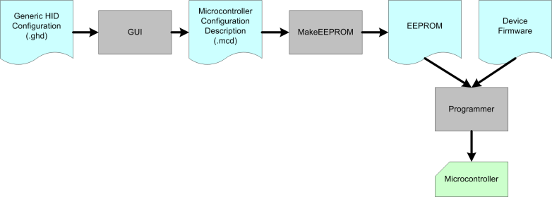
So why is this important? The GUI part of GenericHID doesn't yet support all functionality that an .mcd file can. In particular, the GenericHID GUI has fixed upper limits on KeyMatrix, Rotary Switch and Coded Rotary Switch sizes. If you need to exceed these limits, you need to use an .mcd file.
The export command will save the current GUI configuration as an .mcd file. This is a one way export; the .mcd file can only be imported directly into the programming stage. It can't be visually edited again.
The exported .mcd file can be edited using a text editor. It is xml. The schema is documented here, in plain speak.
After the .mcd file has been changed, it can be imported using the Import and Program command.
Importing
The Import and Program button will import an mcd file, verify it, create the EEPROM, then enter the program dialog. The regular programming process can then be used to program the Generic HID with the .mcd configuration.