PWM - Pulse Width Modulation
The PWM control is used to generate a PWM output signal on an output port. A PWM signal is a pulse that repeats at a fixed frequency. The width of the pulse can be varied from 0 to 100%.
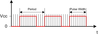
The image above shows the PWM signal, plotting the output voltage against time. The period specifies the time the pulse repeats. The frequency of the signal is 1 / period, where the period is in seconds. In the example above, the pulse width, or duty cycle, is about 66%.
The frequency of the PWM signal and the resolution of the pulse width are defined as characteristics of the microcontroller. See the section on timers for more information.
The frequency of the PWM signal can be configured to be anything from 0.1Hz to 4MHz. For controlling LED brightness anything above 1kHz is fine.
So what is a PWM signal used for? In a HID device, they can be used for driving LEDs and other external loads. Hooking up an RGB LED to 3 PWM outputs will give infinite colour control of the LED. The PWM signal can also be used to adjust the brightness of an LCD backlight. Beware of the current limitations of the microcontroller - it is not powerful enough to drive the LCD backlight directly. A switching circuit using a transistor of FET should be used. For example...
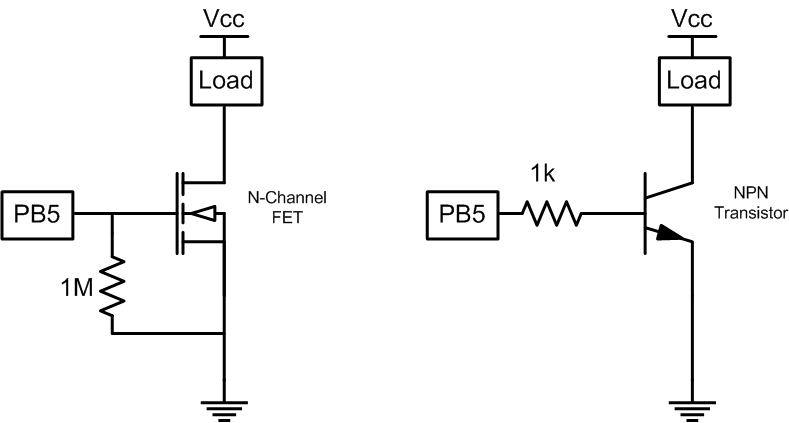
A suitable NPN transistor or N-Channel FET should be chosen that can handle the current requirements. Transistors are recommended because they are less susceptible to static electricity damage.
A PWM component must be connected to a PWM compatible pin, one of: PB5, PB6, PB7, PB4, PD1, PC6, PC5 or PC4.
Properties
Name
Components can be given an optional name. This is seen in the Test tab. Not all applications support the name. Hidcomp/hidconfig supports names.
UsagePage/Usage
The UsagePage and Usage of the Timer. See Usages for more information.
Frequency
The frequency of the PWM output. This is defined in the microcontroller timer setting, shown here for convenience.
Resolution
The number of integer subdivisions the PWM period is divided into. This is defined in the microcontroller timer setting, shown here for convenience.
Timer
Which microcontroller timer this output is connected to. This is dependent on the pin that the PWM output is connected to.