Coded Rotary Switch
A coded rotary switch, or coded rotary selector switch, is used to select one of several options. This device is similar to the regular rotary switch, except the outputs are binary encoded to save on pin requirements.
A rotary switch and a coded rotary switch are shown below.
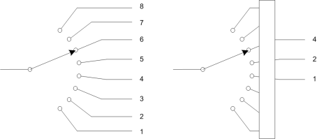
The obvious difference is the number of pins that are required. Because the coded rotary switch uses binary encoding of the outputs, only 3 pins are required, compared to 8.
As with the rotary switch, the common leg of the component should be run to ground and the outputs run to Generic HID pins.
The rotary switch will appear on the HID device as an input with values that range from 0 to outputs - 1.
Properties
Name
Components can be given an optional name. This is seen in the Test tab. Not all applications support the name. Hidcomp/hidconfig supports names.
UsagePage/Usage
The UsagePage and Usage of the Coded Rotary Switch. See Usages for more information.
Outputs
The number of outputs on the selector switch. This is the values that can be represented, not pins. For example, a decimal selector switch has 10 outputs and a hexadecimal selector switch has 16 outputs. Both, however, require 4 I/O pins.
Pull-up
Selecting this enables the internal pull-up resistor of the microcontroller. This is the normally setting. See Mechanical Switches for more information.
Debounce (ms)
Waits for the mechanical switch stop bouncing before registering a switch closure. Enter the time to wait in milliseconds. See Mechanical Switches for more information.
Current
Defines the amount of electrical current used by the switch in mA. This is used to estimate the USB power draw. See the section on Power for more information.
Current drawn by switches is usually insignificant and can be set to 0.