Timers
The microcontroller used by Generic HID, the Atmel AT90USB1287, has built in peripherals called timer/counters. As their name suggests, they can be used as timers, counters, and generators of precisely timed output patterns. Generic HID uses the timer/counters to produce the PWM output signals.
There are 4 timer/counters...
| Timer | Use |
| Timer/Counter 0 | Used internally for timing tasks. Also used to generate the Counter output. |
| Timer/Counter 1 | Used for PWM output. Timer/Counter 1 generates PWM signals for outputs PB5, PB6 and PB7. |
| Timer/Counter 2 | Used for PWM output. Timer/Counter 2 generates PWM signals for outputs PB4 and PD1. |
| Timer/Counter 3 | Used for PWM output. Timer/Counter 3 generates PWM signals for outputs PC6, PC5 and PC4. |
As can be seen in the table above, individual timer/counter units generate outputs for more than one output pin. Timer/Counter 1, for example, can generate 3 outputs. This means the groups of PWM outputs share the timer settings, in particular, the PWM frequency and the PWM resolution.

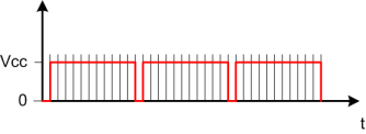
The PWM frequency is the rate at which the pulse is repeated. The period, 1/frequency, is the time it takes for one of these cycles. The PWM resolution specifies the number of discrete intervals the PWM period is broken in to. The resolution is used to determine the length of the PWM pulse. In the example above, the PWM resolution is 12. The PWM pulse width is 8 (66%). The the higher the resolution, the more fine control there is over the pulse length. Unfortunately, the frequency is related to the resolution.
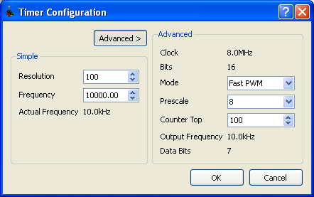
The Timer Configuration dialog is used to set the parameters that define the Resolution and Frequency. In simple mode, shown below, the required resolution and frequency are entered, and the dialog will try to find the closest match.

In Advanced mode, the low level parameters are entered directly to configure the frequency and the resolution.

The parameters in the advanced section are...
Clock
The clock speed of the internal microcontoller. This will always be 8MHz.
Bits
The size of the timer/counter in bits. Timer/Counter 1 and Timer/Counter 3 are 16 bit timers meaning they can count from 0 to 216-1 (65535). Timer/Counter 2 is only 8 bit; it can only count to 28-1 (255).
Mode
Internally, the timer/counters can operate in various modes. Two of the modes, Fast PWM and Phase Correct, are offered as options.
Fast PWM is a straight forward up counter. It counts to "Counter Top", then starts again from 0. At 0, the pulse is turned on. It is turned off at the pulse width. This is shown below.

Note that Fast PWM has a limitation. It is not possible to set it to always on, that is set pulse width to 100%. It will always be one count short as shown below.

The problem is exaggerated in the image above because the "Counter Top" value is low. This usually wont cause a problem, but if it does, Phase Correct mode can be used.
Phase Correct mode is an up/down counter. It counts from 0 to "Counter Top", then counts back down to 0. The PWM pulse is toggled as the counter passes the pulse width mark. This is shown below...

The obvious difference is, given the same Counter Top value, Phase Correct mode will be half the frequency of Fast PWM mode. Phase Correct mode doesn't have the problem of not being able to run at 100%. A 0% pulse width will be all off, and a 100% pulse width will be all on.
Prescale
The prescale is a divisor applied to the system clock. The prescaled clock is then used by the counter to count.
Counter Top
As descibed above, the timer/counters count. They count up to "Counter Top", then restart, in Fast PWM mode, or count back down in Phase Correct mode.
Counter Top serves two purposes; it acts as a divisor to set the frequency, and it determines the PWM resolution.
As a frequency divisor, Counter Top is combined with the prescaler and mode to determine the frequency. The frequency is..
| Frequency = | Clock |
| Prescaler * Counter Top * (2 if in Phase Correct Mode) |
The resolution is defined as Counter Top. A Counter Top value of 100, will have a resolution of 100, that is, the generated pulse can be 0%, 1%, 2%, ..., 100% of the period wide.
Output Frequency
This is the computed output frequency of the PWM signal, as just discussed. It is the actual frequency that will used, given the current parameters.
Data Bits
Data Bits specifies the size of the output variable that Generic HID exposes. This is the size of the binary variable required to hold the "Counter Top" value. This is just for information.