LCD - Character based LCD Display
Generic HID supports character based LCD modules that use the common HD44780U or equivalent driver chip (this is most 5x8 or 5x7 character based dot matrix displays). These displays come in sizes from 8x1, up to 20x4 and 40x2. There are 40x4 displays, which are basically two 40x2 displays, and currently, must be treated as two separate displays.
An LCD has a large number of pins that must be wired to the microcontroller. Any LCD pin can be wired to any microcontroller I/O pin.
LCDs can work in 4-bit mode or 8-bit mode. In 4-bit mode, only half the number of Data pins are required. LCD I/O pins D0..3 are not needed and should not be connected. Yes, the low numbered pins, 0..3 are the ones not needed. This saves 4 I/O pins, at the slight expense of speed, but it is generally not an issue.
LCDs are the only components in Generic HID that can share wires. The pins RS, R/W, D0, D1, D2, D3, D4, D5, D6, D7 can be wired to multiple LCD devices forming a data bus. The only pin that can't be shared is the E pin. E is the enable pin. It tells the LCD that data on the bus is for it. This way a large number of LCDs can be wired to Generic HID.
Here is an example of two LCDs wired in Generic HID...

Note that the LCD wires are sharing pins on the microcontroller, except for the E pins (red wires). They have their own I/O pins. Also, during testing I found one LCD display that did not work properly when sharing data lines. It had to be separated to make it work properly.
LCDs are pretty easy to wire up, but there a couple of gotchas.
First, most LCD displays run on 5 volts. A stock USB Key only provides 3.3v. Unless the LCD works with 3.3v, the USB key will need to be modified to provide 5 volts.
Secondly, the backlight. Most LCDs have some form of backlighting, typically LED. These can draw large amounts of current, sometimes over 250mA. A USB device, as described here, must be careful when drawing this much current. The LED back light must only come on after the USB connection has been successfully established. A method to limit the current must also be used. The backlight current can also be reduced from what is recommended in an LCD datasheet. Backlights that are documented as requiring 250mA, usually run fine on 100mA. Experiment and see.
Contrast
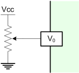
The pictures above show the wiring that is required to connect an LCD to Generic HID. Apart from the power (VCC or VDD) and ground (GND or VSS) a standard LCD Character Module will have a pin used to set the contrast of the LCD display, VO, VLC or VLCD. This requires a potentiometer wired to this pin and, power and ground. A cheap 10k trimmer potentiometer is adequate. Schematically, it should be connected as follows.

USB Interface
GenericHID implements a subset of the standard USB HID specification for character display modules. The following reports are implemented. This is included only if you wish to program your own device. This information can be retrieved from the HID descriptor reports.
USAGEPAGE_ALPHANUMERIC_DISPLAY:USAGE_ALPHANUMERIC_DISPLAY

    // Output Report to display text
    USAGE_CHARACTER_REPORT
	USAGE_COLUMN		    // column number
	USAGE_ROW		    // row number
	USAGE_DISPLAY_DATA	    // display text (one full row)

    // Feature Report to return display attributes
    USAGE_DISPLAY_ATTRIBUTES_REPORT
	USAGE_ROWS		    // number of rows
	USAGE_COLUMNS		    // number of columns

    // report to set a user font
    USAGE_FONT_REPORT
	USAGE_DISPLAY_DATA	    // the character index (0-7)
	USAGE_FONT_DATA		    // 5 bytes of font data, bit packed
Properties
Name
Components can be given an optional name. This is seen in the Test tab. Not all applications support the name. Hidcomp/hidconfig supports names.
UsagePage/Usage
The UsagePage and Usage of the display. See Usages for more information.
Note- for an LCD display, this is fixed and cannot be changed.
Rows
The number of rows on the Display.
Columns
The number of columns on the Display.
8 Bit
The number of data lines to connect to the LCD. If true, 8 bits are used (all data lines D0-D7). If false, only 4 bits, data lines D4-D7, are used.
Row1Address
The start address of row 1.
Row2Address
The start address of row 2.
Row3Address
The start address of row 3.
Row4Address
The start address of row 4.
Current
Defines the amount of electrical current used by the LED in mA. This is used to estimate the USB power draw. See the section on Power for more information.
LCD displays use very little power to display the LCD text, typically 1-2mA. The LCD back light, however, are generally power hogs.