Digital Encoder
A digital encoder is a rotary control that encodes its output as a sequence of pulses. Generic HID supports rotary encoders that output their movement as incremental quadrature code. Digital Encoders typically have the appearance of a panel mount potentiometer, or a machine control dial.
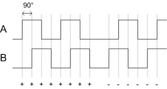
A Digital Encoder has two outputs, A and B. These make up the "waveform" of a quadrature signal, with the A and B waveforms out of phase by 90°. Only one signal ever changes at a time, and from this, Generic HID can determine if the encoder is moving forward or backward.

Digital encoders must be connected to Interrupt ports, that is, one of PE4..7, PB0..7, PD0..3.
The Generic HID represents the digital encoder as an 8-bit input, with wrap around. This means it will count up to 255, then wrap to 0 (or down to 0, then wrap to 255). It is up to the application using the device to then make use of this information. Hidcomp/hidconfig handles this information correctly.
Care must be taken with the current consumption of digital encoders. The larger industrial encoders can draw 100mA, which can overload a USB device. See the section on USB Power for more information.
There is currently limited support for mechanical encoders. Mechanical encoders are a cheaper version of the digital encoders, that generate the A/B signal through mechanical contacts. Pull-up resistors are supported, but to work correctly, debounce processing should be used process the A/B waveform.
Properties
Name
Components can be given an optional name. This is seen in the Test tab. Not all applications support the name. Hidcomp/hidconfig supports names.
UsagePage/Usage
The UsagePage and Usage of the Digital Encoder. See Usages for more information.
Bits
The size of the encoder counter in bits. GenericHID supports up to 16 bit numbers meaning they can count from 0 to 216-1 (65535). The counter will wrap around the minimum/maximum values.
Depending on the software reading the values, 8 bits is usually enough.
Output
The type of output reported back to the host computer. This can either be Absolute or Relative. Absolute is described above, that is, the microcontroller will keep track of the encoder count, up to "Bits" size. In relative mode, the number of counts that have changed between packets is reported to the host computer. This will be 0 if the encoder is steady, or a small positive or negative value if it is moving. It is the host computer's responsibility to keep count.
Pull Up
Selecting this enables the internal pull-up resistor of the microcontroller. This is not required for digital encoders. It may be used with mechanical encoders but may not work correctly because of the lack of debounce processing.. See Mechanical Switches for more information.
Current
Defines the amount of electrical current used by the LED in mA. This is used to estimate the USB power draw. See the section on Power for more information. As mentioned above, industrial style dials can use a large amount of current.