USB Hardware
USB Devices
Generic HID will work with any at90usb1287 development board (probably at90usb1286 too, but not tested). The cheapest, although not easiest to use, is the AT90USBKey.
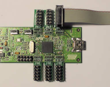
AT90USB Key
The AT90USBKey is made by Atmel as a demo board to show off the functionality of the at90usb1287. As a USB demo board it comes with chips to show off the devices ability to act as joystick, mouse, memory stick, and HID device. The biggest advantage of the device is its prices, $US30. Its biggest disadvantage is the headers to access the I/O pins.
The photo below is a close up of the AT90USBKey, showing the holes for the I/O port header on the left, and the holes for the JTAG programming header on the right.

The JTAG programmer has regular 0.1" x 0.1" pin spacing. These are common header pins that can be found every where. They are spaced wide enough that they can be soldered to directly.
The I/O pins, however, are another story. As can be seen in the picture, they are tightly spaced. They use 0.1" x 0.05" pin spacing and incredibly difficult to solder to directly. Firstly, the holes are tiny, so you need to use thin wires to be able to thread them through the holes. I recommend you DONT tin the wires before inserting them. Strip them, twist the strands, insert, then solder and trim. Secondly, because they are close together, it is very easy to bridge two holes with solder. This won't be a problem of only a few of the pins are used. In my testing, I was using most of the pins and I made a terrible mess of the soldering. So what's the solution?
Connectors
Connectors for the AT90USBKey I/O pins are hard to find. When I first started looking, the only thing I could find were latched 90 degree headers and mating IDC connectors from mouser, #571-5-104069-4 and #571-2-111196-5. The headers are too wide to be placed side by side, so they must be alternated on each side of the board. The IDC connectors us 0.025 pitch ribbon cable which is twice as dense as regular ribbon cable. This option is expensive; $1.30 for the header, $3.97 for the connector - for 6 ports, 6 x (1.30 + 3.97) = $31.62 plus some ribbon cable. This is more than the board cost.
Below, the picture on the left shows the headers alternating from top to bottom. The middle picture shows the connectors in place. The photo on the right shows what I use on the end of the ribbon cable. I only got as far as prototyping with this combination, so I needed something to plug into a breadboard. Note the numbering of the I/O pins is not consecutive. This is because the connector was mounted on the bottom, not on the top.
 |
 |
 |
There are now other sources of pins and headers. Digikey now sell headers and connectors, but I have not tried them. Is suspect there will still be a problem inserting them side-by-side. The problem is usually with the connector, rather than the header.
Wizbang Wings
Another option to using the wizbang wings, made by Wizbang Designs. These are small printed circuit boards adaptors that are soldered over the top of the AT90USBKey I/O ports to provide standard 0.1" x 0.1" headers. These are easy to solder to, and accept the standard 0.1" pitch headers and connectors that are available from all good electronics retailers.
Thanks to Andr� van Schoubroeck for pointing out that Wizbang Wings style adaptors are also available from 2 Bit Micro - Set of 6 2BM-10017 AT90USBKEY Adapters
 |
 |
 |
The image on the left shows the wizbang wings. They come as a set of 6 (only 4 shown) in a snap apart board. The middle image shows the wings installed. The image on the right is shows 0.1" pitch headers installed, with a 10 way IDC connector and ribbon cable attached.
Little PCB "winglets" are still tedious to solder. You need a steady hand, a fine tip soldering iron, and good eye sight; I have a fine tip soldering iron. But once installed the board is easy to use.
At the time, the wings cost about $6.00 from memory, however, when I went back to check the prices, the site looked parked. Whispers are the owner is off on a secret international mission somewhere.
DIY Boards
Another option is to make your own board. If you can make PCBs and do surface mount soldering, the design of the board is quite simple. Here is a link to my Custom GenericHID Board.
Reclaiming AT90USBKey Pins
Because this is a demo board, there are other peripherals attached to the board. While these parts remain, 22 of 48 I/O pins can't be used. By attacking the board with a soldering iron, 17 can be freed. The parts to be removed are usually very small and sensitive, but we don't care; they'll never be replaced. Just get a regular soldering iron, and heat them. If you heat the middle of a small component, like a resistor, the solder on the end will melt and you can just flick the part off the board. The same technique can be used for the memory chips. They are a bit larger, but with enough heat, they will fall off. Beware of the nauseous fumes. Make sure you do this in a well ventilated area.
When the parts are removed, remove the excess solder with a some de-solder braid.
Temperature Sensor
An NTC Thermistor is connected to IO pin PF0. Remove resistors R27 and R29 to reclaim this pin.
Battery Voltage Monitor
A pair of resistors form a voltage divider used to monitor the voltage of the external power supply. This is connected to IO pin PF3. Remove resistors R28 and R30 to get this pin back.

Flash Memory
The flash memory must be removed if the voltage of the board is to be changed to 5 volts. There are 2 flash chips, U2 and U3, and two resistors, R9 and R10 that must be removed. This will reclaim IO pins PE0, PE1, PB1, PB2, PB3.

LEDs
There are three LEDs on the board. One is a single colour LED that is lit when the board has power. It isn't connected to any IO pins. This can stay.
The other two LEDs are tricolour LEDs that take up two pins each. These are optional. They can be left to show the board status: Red: not ready, Green: go. This default functionality allows them to be used to switch High Power Devices. I chose to leave one as an indicator.
LED1, D2, can be removed to free up IO pins PD4 and PD5.

LED2, D5, can be removed to free up IO pins PD6 and PD7.

UVCON, PE7
The AT90USBKey has support for switching to a 5 volt bus when running in host mode. As we never run in host mode, we can reclaim IO pin PE7 by removing resistor R25.

Buttons and Joystick
The push buttons and joystick device are switches. When activated, they short the IO pin to ground. Therefore, if they are not activated, they will no cause a conflict. There is no need to unsolder them. The joystick IO pins PB5, PB6, PB7, PE4, PE5 can be reclaimed.
Just a word if caution. There are two buttons on the board. One is connected to the microcontroller reset pin. There is no point removing this as the pin can't be reused. The other, the HWB button, is connected to IO pin PE2. This is the Hardware Boot Loader button. If you press the Reset button, then the HWB button, then release the Reset button, then release the HWB button, the microcontroller will enter USB bootloader mode. It is highly recommended you leave this button for recovery if the software bootloader fails. The pin can still be shared, preferably with another button; something that doesn't change the pin signal unless actioned.
JTAG Interface
The microcontroller has a JTAG interface that is used for programming and debugging the microcontroller. This interface uses up 4 IO pins: PF4, PF5, PF6 and PF7. Unfortunately, these pins cannot be reclaimed without using a JTAG programmer, or an ISP programmer, to switch off the JTAG interface, by unsetting JTAGEN fuse.
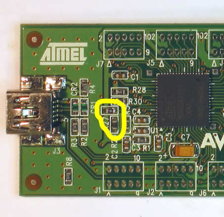
UID
The UID pin on the microcontroller, PE3, is used to externally detect whether the USB is being as a host, or a device. Seeing we are always a device, we can try and reclaim this pin. I say try, because the pin is hard wired to USB connector. To reclaim it safely, the PCB track needs to be cut. This can be done with a scriber, or a dremel, and a very steady hand. If you are game, cut the thin track under the highlighted yellow line.

Hardware Design Decisions
Before you start programming, soldering and unsoldering, a couple of important hardware decisions need to be made, or at least kept in mind about the USB Hardware...
- It can be bus powered, self powered, or both.
- It can run off 3.3 volts or 5 volts.
- It can only draw a maximum of 100mA of current when first plugged in.
- It can only draw a maximum of 500mA of current, and this will usually only be available from a powered USB hub.
- In addition to the USB current restrictions, the AT90USBKey can only supply a maximum of 300mA at 3.3 volts. This limitation is due to the selection of voltage regulator it uses to convert 5 volts to 3.3 volts.
Based on what components you are planning to connect to the key, following decisions need to be made.
Bus or Self Powered
The USB key supports being powered via the USB Bus, or via an external power source.
Being Bus Powered means that the microcontroller and all components connected to the controller are powered by USB power coming from the USB cable. This is convenient because it means you only need one cable running back to the computer. However, you are restricted to 3.3 volts 300mA if you use the stock hardware. If you are willing to hack the hardware, you can get 5 volts, 500mA maximum. You will probably also need to connect the device to a powered USB hub to get the higher current.
Being self powered means that an external power supply is used to power the microcontroller and components. This allows more than 5 volts to be used. Fortunately, the AT90USBKey already has the hardware in place to support self powering. All that is needed is an external voltage source from 8 volts to 15 volts, connected to the 2 pin power connector. A short adaptor cable is provided with the AT90USBKey that is normally connected to a 9V battery. This can be used to connect the external supply. Being self powered unfortunately means a second power cable must be run to the board.
Bus Powered or Self Powered must be selected in the Properties of the microcontroller in the Generic HID software.
Voltage
The stock USB Key is configured to run off 3.3 volts. It can be modified to be run off 5 volts by making modifications to the board. The voltage regulator can be removed and tracks short circuited so that the USB Bus voltage, 5 volts, is now the board's power source, VCC. If this is done, the Flash memory must be removed as this only runs up to 3.6 volts.
The USB specification states that the data lines of the USB cable must be between 3 and 3.5 volts. The AT90USBxxx chip has an internal voltage regulator that can provide these values if the microcontroller isn't powered by 3.3 volts. However, this is an internal configuration of the chip, and must be programmed BEFORE the voltages are changed.
So when is 3.3 volts enough? It depends on the components connected to the USB Key. Passive devices like switches and potentiometers (joysticks), will run fine on 3.3 volts. LEDs will as well. It starts to get tricky with more complicated devices. The LCD displays I have played with required 5 volts to run properly, but the logic interface worked fine at 3.3 volts. The LED backlight for the LCD required 5 volts, and 300mA. The rotary encoders I used also worked at 3.3 volts, although the specification sheet said 5 volts. The bottom line; test it.
To change the device to run off 5 volts (this works for bus powered and self powered devices)...
- Use the Generic HID Device software to create an empty configuration with only the AT90USBkey.
- Set the device voltage to 5 volts. You can also specify if the device is bus powered or self powered.
- Reprogram the device.
- Un-solder the 3.3v voltage regulator, U4, then place a wire link across pins 1 and 2. The pins are so small
and close together that a blob of solder should suffice.
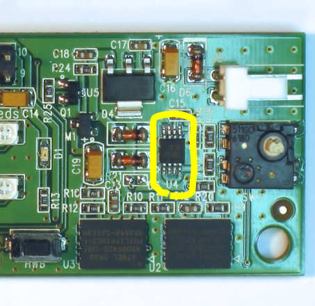
- Un-solder the diode, D3, and replace it with a wire link.

- The completed board should look like this...

- Done. The device is now 5 volts. Don't forget to remove the flash memory chips before you power it up again.
Current
The USB specification limits the current draw from the bus to 100mA when it is first connected. After the device is recognised by the host PC and it has completed its handshaking, up to 500mA can be drawn (or 300mA for a stock AT90USBKey). More then 500mA must be provided by an external power source.
For configurations that require less than 100mA, there is nothing to do. Connect the components and go.
Over 500mA, an external power supply must provide the power.
Devices that draw over 100mA but less than 500mA from the bus are called High Power Devices in USB speak. These devices must switch their components power on only after the device has been recognised and configured. Part of the device to host handshaking sequence requires the device to upload several pages of configuration information. This includes if the device is bus powered, and what the current draw is. If the power requirements are too much for the host PC, it can choose not to start the device.
On my USB Pendant, I implemented this using a P-Channel FET to switch the high side power to the power hungry devices. The resistor will keep the FET off while the microcontroller starts up with tri-state IO pins. When I did it, I piggy backed the circuit on the status LED2, pin PD7. PD7 (Red LED) is Hi-Z while the microcontroller initialises, then is set high, to Red, while the device is starting. If the device starts successfully, the Green LED is enabled and the Red turned off. Bring the Red LED low, will enable the power.

An alternative is the soft-start version, which brings the power on slowly after the power is enabled...

Summary
What the?
How much current do I need? Check the data sheets of each component and add them up.
How much voltage? Check the voltage requirements of each component. They should all be 3.3v, or all 5v. Mixed 3.3v and 5v can be done, but requires advanced electrical knowledge.
|
I need... |
Solution | |
|---|---|---|
| Voltage | Current | |
| 3.3 | < 100mA | Nothing to do. Use the stock board. |
| 3.3 | > 100mA and < 300mA | You need to switch the power to the external components using a switching circuit like the one above. |
| 3.3 | > 300mA | The onboard voltage regulator will not provide enough current at 3.3 volts. You may be able to try a combination where the microcontroller is bus powered, and the power hungry devices are powered by an external supply. |
| 5 | < 100mA | You need to program the device to tell it is 5 volts. Then you need to remove the voltage regulator. |
| 5 | > 100mA and < 500mA | You need to program the device to tell it is 5 volts. Then you need to remove the voltage regulator. Finally, you need to add the switching circuit above to control the power to the external components. |
| 5 | > 500mA | You need to program the device to tell it is 5 volts and Self Powered. Then you need to remove the voltage regulator. Then power the device via the external connector. The external power supply must be a clean 5v regulated supply. |